
The 40m Loop antenna Ed, VK2JI
(This antenna is also known under the names “Sky Loop” and “DX-Buster” and is very similar to a horizontal delta loop).
The following is an article which I wrote and was published in the February 2013 edition of the Central Coast ARC “Smoke Signals” magazine.
My interest was aroused by an article from Ray Howes, G4OWY in the October 2012 WIA Amateur Radio magazine entitled “80m or 40m to 10m – just one loop fits all”.
He goes on to describe a full wavelength horizontal loop antenna that he suspends from two trees and two points on the back of his house. The big disadvantage of this antenna is its physical size – especially if you build the 80m or 160m versions. I could just squeeze in the 40m version with it’s roughly 11m metre sides, but not if I allowed for the support ropes in Ray’s design, so mine is a revised version of the design with no insulating ropes or egg insulators. As my intent was to use this as a portable antenna, the lower the number of the parts the better. Of course being portable, you can choose a location with trees – whether you’d find a site with trees nicely about 11 metres apart in a square however is another matter!
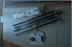
Antenna components
So I’d like to install and test in my small garden and have a solution that I can take out and set up easily portable. The answer … an Aussie favourite – telescopic squid poles. So I ordered 4 x 5m heavy-duty Squid poles and 4 metal post bases for them. I chose the 5m rather than 6,7 or 9m ones simply on price (the 9m ones also wont fit the base poles). If this all doesn’t work I don’t want to have wasted too much money. If you want to make this aerial at an even lower cost bamboo poles can be used in place of the squid poles but they would be less suitable for a portable configuration. (Thanks to Graham, VK2GRA for this suggestion).
The posts will fit into the corners of my garden and the squid poles go into them. Being fibreglass these posts don’t have an impact on the antenna, so why use insulators? The wire is simply wound a couple of times around the rubber caps on the top of the squid poles and taped there with electrical tape to stop it slipping down as the pole is raised.
Now what about the antenna wire? Yes with such a large antenna you need a long lengths of wire – about 43-45m for the 40m version. Ideally it should be copper wire (yeah sure! Have you seen the price of copper?). Looking for a cheap option, I looked on eBay and found what I thought would do – flexible garden wire in a 50m roll. $12. Not $12 for one roll, $12 for 15 roles! Oh well it’s cheaper buying these 15 rolls from here than one roll elsewhere and I can also give these away to others wishing to build the antenna.
So what else do we need – ah yes, some way to connect the co-ax to the garden wire that is light but stable. The co-ax outer goes to one end of the wire, the inner to the other end. Well I considered a piece of plastic kitchen board but when the squid poles arrived they came with some blue plastic tubing that had been used simply as packaging material. I cut a small piece off one of these, bought some screw terminals from Jaycar grabbed a short piece of 50 ohm coax and a SO-239 line socket and all was set (see pictures below).

I was rather proud of this solution. It is strong and looks tidy (the screw terminals are offset other wise they would short inside the unit).
So now it’s time to test, all the parts have arrived, I had booked out the clubs antenna analyser so every-thing was ready. Initially I thought I’d just check how stable the squid poles were in their mounts (I don’t guy these as the antenna wire holds them together)
They were fine once I added some rubber bands to close the open side of the top of the holding poles. As it was still light I decided to start and put up the antenna. The biggest problem was the garden wire twisting and kinking so that I couldn’t get a straight run out but after about an hour all was unwound attached to the squid poles – the SO239 unit attached between the wire with the length longer that I expected I’d need (but not yet cut), and the coax was connected to the antenna analyser and everything was ready to go.
My first tests on the antenna showed it was at resonance at about 6.6MHz – no worries drop the one pole down, shorten the wire and test again. This time it was 6.8MHz, OK I can take a lot more off …. Next attempt still 6.8MHz – No wait …. 8.6MHz ! I cut it too short. Oh well while this is a test (and I have plenty of spare wire once I get it right), I attached part of the wire that I had cut off and tested again and after a couple more attempts, I get the antenna nicely resonant across the 40m band.
By this time it’s getting dark and cold, so I disassembled everything and headed inside. One disappointment was although there was a dip at resonance it was only dipping the SWR bridge down to 3:1. While wondering what I need to do about this, upon reading the G4OWY article again, I see that he said the best he could get was 3.1:1 so I hadn’t done anything wrong, this antenna seems to need an ATU because of the bad SWR.
 I wasn’t happy with this however, so I went looking on the Internet to see if the antenna might give a better SWR with a Balun or some other solution. Which is when I came across the article “Full Wave Loop Antenna” by WH2T. (http://www.designerweb.net/downloads/80m_Full_Wave_Loop_Antenna.pdf )

Reading this article I again heard how much better the loop is to a dipole or a vertical with 2.1 dbd of gain, a lower noise level and broader bandwidth. So my enthusiasm came back, but what about that 3:1 SWR?
Reading further in the article (which covers loops up to 160m and how to calculate the size for any frequency) I found that the author had found a way to address the SWR by using a “Q section” simply introducing a 75 ohm length of co-ax before your normal 50 ohm feed. The loop has a nominal impedance of 100 ohms – no wonder I was getting a 3:1 SWR. The length of the Q section depends upon the frequency the loop is being built for and the velocity factor of the coax you use.
Formulas to calculate the required length of the loop and this Q section are at the end of this article.
I took a look in my shed for some 75 ohm coax and came back with some meant for satellite dish connection. I managed to find data about this cable on the Internet and the important information – its velocity factor – which is 0.8.
Upon calculating the length needed, I could not believe it but the length I had was exactly what is needed!

So now it was time to disassemble the connection de-vice that I was so proud of and connect the far longer section of 75 ohm coax in it and have the SO239 hanging loose on the end of the co-ax.
 On my next test – Success – or at least marginally better with the length of 75 Ohm co-ax than without – I now have an SWR of between 2 and 2.1:1 at resonance. I had also replaced the antenna wire with one of the other 50m rolls of garden wire and cut the length exactly using the antenna analyser.
This was a “quick” Friday lunchtime test, but I still had chance to bring the FT-757 out to the deck and connected it up to see what I could hear and work on 40m – one of the worst days for propagation on 40m during the day for some time. All I heard was a VK3 complaining that conditions were terrible! Well I checked transmit as well with up to 100W and the garden wire took it OK, with that 2:1 SWR. Next test will be at the weekend when hopefully conditions will be better, a few more people are around and I can run a direct comparison between the loop and my trapped wire dipole.
Well, the weekend came and my chance to perform a real comparison over my other antennas of the “DX-Buster” 40m full wave horizontal loop.
Everything went back up – the squid poles, the garden wire, the Q-Section 75ohm coax etc. In fact this time I moved two of the squid pole bases out a little to try to get rid of the slack in the wire to try to get each leg horizontal. I got it better but not yet perfect. I ran a length of coax back to the shack and checked SWR – horrible! I traced the fault to the SO239 line socket on the end of the 75 ohm lead and did a temporary fix (later remaking the connection properly).
I tuned around on 40m and immediately it was obvious I got a lot less background noise than on either my SRC X-80 vertical or my Rippletech trapped wire dipole antennas. The signals may have been a little stronger as well but the main thing was with the lower noise level, they were a lot, lot easier to listen to.
So how about a transmission test. SWR now is good, just under 2:1. I interrupted John VK2FJKH and Pete VK2FMSL on the 2m repeater and asked if they could possibly QSY to 40m and see what kind of a signal I was putting out and they kindly agreed to do so.
After putting out a call there, not only did John & Pete come back but also Arthur VK2FHAY, Dave VK2FEAA and Pat VK2AAE. All of whom, I could hear far better than ever before. Even Pat with his antenna laid on the ground and down at S2-3 was fully readable because of the lower noise floor.
This was a very successful test and I could conclude that the Loop in the back garden was better than either of my other two antennas, perhaps because it was further away from the in-house electrical noises but I think it is more than that. It also is the first HF antenna that I have found that allows local communications.
I then decided to try the antenna on other bands, I knew 20m was resonant, I had seen that previously on the antenna analyser, but would 10m also be? What about the WARC bands – they shouldn’t be resonant, should they? Just using the built-in ATU in the TS- 2000 to tune the antenna, it worked well on 20m, 10m and 15m. It even seems to work fine on 12, 17 and 30m although all I could find there was digital & RTTY signals and a bit of CW (well this was mid-afternoon still) – but it WORKED with an SWR under 2:1 on all of those bands! I could even hear the test Morse transmissions on 3.7MHz – and this antenna shouldn’t work on 80m, it’s a 40m loop. Although the SWR on 80m was OK 2.5:1 it really does not perform well there, that would need the 80m version. The antenna would not tune with the ATU on Top Band (160m) – I would have been extremely surprised had it worked there!
So what now? Now that it is clear that the antenna does indeed work, I’ll look at moving up from the 5m squid poles to the 7m ones, the extra height should bring extra gain. I also need to move the bases out a little more to make the wire actually horizontal all the way around the square “loop”.
One thing is for sure, this antenna works very well for such a simple antenna. It’s an antenna that anyone can build. Having the antenna analyser on hand to set the correct garden wire length is the only technical issue however that’s an advantage of being a member of the CCARC club, we have one that is loaned out to members.
There is no reason I can see that 80m, 160m and 20m versions of this antenna should not work as well as this version. Of course for the 80 & 160m versions you need a lot more space – perhaps keep those options for when operating portable? Perhaps make 40,80 & 160m wire lengths and keep them available to put up whichever version of the antenna is needed when out portable, i.e. one set of poles with three different antenna options?
Improvements to the basic design:
While the article above describes a working solution, the action of running out the 40m plus length of wire each time I wish to raise the antenna becomes a pain as the garden wire ties itself in knots. So I wondered if I could rig some way of having the wire for each side of the square as separate lengths, so making setting up and taking down much easier.
I decided that using more of the screw terminals on the plastic tubing at each squid pole would be a practical option, so I made up three more tubes each with a terminal, cut new lengths of garden wire each ¼ the length of the first antenna wire. Put everything up and guess what … the antenna was no longer resonant on 40m, it was down around 6.6MHz, so with the help again of the club’s antenna analyser, I trimmed back each wire in turn and after taking between 4 and 5 inches off each of the “elements”, we’re back resonant on 40m and 20m. Testing again showed a great signal to noise ratio when compared to the dipole.
In all tests up until now, I have simply taped the coax connection point plastic tube (and now the “element” connectors) to the top of each squid pole. This is fine for a temporary set-up but the tape dries up and they simply don’t look good. So I have now filed down the rubber balls on the top of the squid poles, so that they can go inside the plastic tubes (stopping going through when they hit the screw at the back of the screw terminal). In the case of the co-ax connection point this meant I had to move the coax so that it came out of the top of the tube instead of the bottom.

So now I have an easier to assemble but still as good performing 40m full wavelength horizontal loop antenna that I can put up in about 20 minutes and take down in 15.
FORMULAS:
Loop:
To determine the approximate length in feet of a Full Wave Loop antenna use the formula 1005/Freq in Mhz = length in feet.
For 160 meters a full wave loop antenna resonant at 1.9 Mhz would be about 529 feet long.
For the 80 meter band a full wave loop antenna resonant at 3.85 would be about 261 feet long. A full wave for 3.9 Mhz = 257 Feet 8 inches.
These length antennas may require some pruning or trimming of the wire to obtain a low VSWR. But if you measure carefully you should get very close.
Q-Section.
IMPORTANT – Connect the shield of a “Short Piece” of 75 ohm coax to one end of the loop antenna , Connect the centre of the 75 ohm coax to the other end of the loop antenna. The length of the 75 ohm coax is quite important. It will be used as a Q section to match the loops 150Ω impedance to the coax to the rig with a 50Ω impedance.
To determine the length to use, Use this formula “Length in feet = 246 x VF / Freq in Mhz” VF = the Velocity Factor of the coax. So multiply 246 by the Velocity Factor of the coax , Then divide by the frequency .
If you use RG59 or RG11 with a Velocity Factor of 0.66 , For the 80 meter band the piece of 75 ohm coax will work out to be about 42 feet long. While RG59 and RG11 coax usually has a Velocity Factor of 0.66, foam dielectric coax such as RG6 might have a Velocity Factor of 0.81 or more.
Put an SO-239 line socket on the unused end of the 75 ohm coax, (alternatively if you don’t have an SO239 line socket you can use a PL-259 and screw a PL258 double female coax connector onto this PL259 coax connector). Then connect your length of 50 ohm coax that goes to your transceiver or ATU.
EVEN Better – here’s a web page with the calculator there for you: http://www.66pacific.com/calculators/full-wave-loop-antenna-calculator.aspx
Usage update 16/12/2012:
While this was envisaged to be a portable antenna, to be put up and taken down in various locations, the fact that it performed so well in my tests means that it has been left in position and continued to perform well until today when the SWR went bad. Upon inspecting each of the terminals where I connect the 4 lengths of garden wire, I found rust on both the wire and the terminals. My plan is now to tin the wire ends to protect them and then to wrap the terminals with coax-seal (amalgamating rubber) tape to protect them from the weather.
UPDATE 40 metre loop antenna revisions.
The following is an update article published in 2014 after I moved from Australia to Germany:
The 40 metre loop antenna came with me to Germany and indeed has remained my main antenna doing good service, including 20m SSB contacts back into VK to both fixed and portable QRP stations using long path propagation, that exists between EU and VK around 0800 UTC when conditions are good.
The one drawback of the 40m horizontal loop antenna is it’s need for space and indeed whereas I had an exact (ideal) 11m x 11m garden in Woy Woy, here in Pürgen, Bavaria, I haven’t been so lucky with the result that the antenna is now a triangle rather than a square, which drops 1dB of its gain. It still works well even in this configuration.


When I first re-installed the antenna in Europe, I replaced the gardening wire with “proper” Teflon strengthened multi-stranded antenna “magic antenna” wire, which meant the “loop” had to be a little larger but apart from that the same 7 metre squid poles and my plastic pipe wire routing pieces on top of the poles remained as did the simple feed connections and quarter wave Q-Section to match the antenna down to 50 ohms.
The antenna had some competition for a while, when as a 60th. Birthday present my wife and some close friends bought me a G4MH two element mini tri-bander beam. After some time tuning the elements to frequency this beam went up on a tilt-able mast with my old Yaesu G-250 rotator. While the beam gave some ability to null out some stronger QRM, actual signals on the 10,15 & 20m were better on the loop. I believe the yagi had to be a lot higher than I could safely support with its wind loading, even with a thrust bearing. After some deliberations, the beam came down and was sold and I looked to see if I could further improve the loop. This article covers the things tried on the antenna and the current status of this still truly remarkable antenna given it’s simplicity and relatively low cost.
Height
As the existing squid poles were 7 metres high, the antenna only “peeked” over the top of the surrounding rooftops. In Germany you can install an antenna up to 10m high without needing any planning permission so after searching around for the best value and after viewing a mast at Friedrichshafen, I decided to buy three 10m and one 12.5m telescopic fibreglass poles from DX-Wire. The reason for the 12.5m pole was to remove the two top sections (this is easily done by simply dropping them out of the bottom of the pole) so that I would have a larger diameter and hence stronger top section to support the weight of the feed point and coax. The tops of the 10m poles are rather thin, but as they only have to support the wire, this was expcted to be less of a concern.
I made up some wire loops that went into some crimp connectors which in turn fastened onto clamps on the top of the three 10m poles. The (now 10m high) 12.5m pole got the existing feed-point connector and Q-Section feed coax.
With the antenna at the increased height, I had to extend the length of the loop (less earth capacitance effect perhaps?). This combined with the thinness of the tops of the poles meant that the sides of the loop drooped considerably and I had to move one of the posts out from being fastened to the side of the garage, to being supported by the trunk of one of our three apple trees. I believe signals were stronger with the increased height however with the thin sections at the top of the 10m poles I could never get the loop to “look” right, with the poles leaning inwards and hence causing the wire to droop again.
As two of the poles are located at the edge of my property, I have no way to guy the poles to make them straight. One pole (the one moved to the apple tree) got a cord added to try to help make it a little more vertical and take some slack out of the loop, but that was all that I could do. When a major storm hit, (Niklas – the strongest storm to hit Germany in 30 years) another issue became obvious. These poles whipped around in the wind in a dangerous manner. Even the shortened 12.5m pole was moving a lot in the wind and in fact managed to blow over so far that it got caught up with my 6 metre Moxon antenna which was now mounted on the tilt-over mast. In lowering the poles in the storm, the wire loop came out of its connectors on the feed point (interestingly the wire didn’t break). I managed to dislodge the pole from the Moxon but also bent that antenna in the process.
What did I learn from this? These poles should not be taped at their joints, so that in such a storm, they drop height automatically (this is how I had the poles installed in Australia). These poles at 10m high are simply too flexible, so I had to reduce their height so that they are more stable but the antenna remains high enough to clear the local rooftops.
Parallel feed
 While the loop works very well on 40m (Full Wavelength) and 20m (Double Wavelength), it’s performance on other (even frequency multiplication related) bands is not as good and in most cases requires the ATU to match the antenna. I suspect this is due to the fact that the Q-Section that matches the antenna to the coax-feed is cut for 40 metres. One way to be able to experiment with other matching approaches without having a band specific matching cable on the mast is to install a parallel feed cable (aka Ladder Line) and then match in the shack with an ATU or possibly a balun of some kind. A loop can have an impedance between 100 and 200 Ω depending upon its height above ground and the frequency it is being used on also affects the impedance. Ideally 150 ohm parallel cable could be used but the only way to get such a cable is to build it yourself. Ladder line is normally 450 Ohms impedance with some other parallel cable being available at 300 Ohms impedance. I bought some of the 300 ohm type and made up a lead with the feed-point on one end and free leads to go to an ATU or Balun at the other end.
In short the results of this test were not good, the SWR to the antenna was unacceptable no matter what I tried, so this solution got put in the “it was an interesting experiment” pile of spare cables in the cellar.
BALUN
Normally with HF antennas one uses a BALUN at the feed point to convert the impedance from the antennas native impedance down to 50 Ω for your coax. Such BALUNs work over a wide frequency range (multiple bands). With loops this is less common, partly due to the fact that the impedance is a nominal 150 ohms but as noted above can vary. Based on 150 Ω a 3:1 ratio Balun is needed however most pre-made BALUNs are 1:1, 4:1 or 9:1 (UNUN). It is rare to find commercially made 2:1 and 3:1 BALUNs however I did find a Russian Radio Amateur advertising BALUNs for 2:1 and 3:1 ratios and these were not mounted in any heavy box, rather just the BALUN itself. I know I could have ordered the required Ferrite cores and wire and wired a BALUN myself but at the price offered (US$15 + $7 shipping) I decided to simply buy the already created item. The BALUN was advertised on eBay – here – http://www.ebay.de/itm/Balun-transformer-3-1-1000W-1-8-30-MHz-SWR-1-15-/221837508959?
Once received, it was a short trip down to the local DIY store to get a suitable ($3) housing and with a couple of terminal connectors and a length of coax which I already had, I made up the new feed-point for the loop.

It is interesting to note that the balun uses coax through the two ferrite cores with the centre of the coax forming one winding of the Balun (the “3” part of 3:1) and braiding of the coax forming the other winding. I installed the BALUN on the shortened feed point pole in place of the Q-Section as part of the antenna restoration project after the problems I had with storm damage.
So, is the BALUN option better than the Q-section? It’s hard to be able to give a clear answer as band conditions at the moment are all over the place and the antenna is now at about 8m AGL rather than 10m. I believe the antenna works better on 17m than it used to, 40m and 20m seem about the same and I “think” 10metres is better as well. The built in ATU in the TS2000 can now tune the antenna on all bands from 40m to 10m which it could not do on 17m and 12m before, so I think I in this respect the BALUN may be better than the Q-Section for tuning. Months later however I found I had a relatively high noise level on 40m and did some hunting and got rid of one source (a faulty switched mode PSU in the shack) but still things seemed a little noisy. With the aim of trying the loop as a long wire or top loaded 80m vertical as described below, I put the 75 Ω Q-section back in and noticed straight away a reduction in base noise level floor from the antenna but with signal levels remaining the same. My (current) thinking, therefore, is for anyone looking to install a horizontal loop antenna, use the very cheap Q-section option rather than a BALUN.
As my teacher at my first radio club told me, antennas are not a fixed science, you can always experiment and find something new. For the moment I’m happy with the antenna until I get some new idea of how to improve it …..
References and interesting additional points:
In the article from WH2T – referenced above, the author points out that it is possible to use the horizontal loop as a top-hat on the coax with the coax becoming a vertical antenna even for lower bands than the loop is made for! So a 40m horizontal loop can operate as an 80m top-loaded vertical! My initial attempts to do this were not successful but read the report further down the page about my switched option. Of course YMMV.
 Other sources of information on horizontal loop antennas:
Rob VK5SWs article on an 80m horizontal loop –
http://www.vk5sw.com/Multiband%20Horizontal%20Loop%20Antenna.htm
From W0MHS – http://www.dxzone.com/qsy30908-the-loop-skywire-antenna
Interesting facts gathered on the full wavelength horizontal loop gathered from around the web.
- As with most antennas under 1/2 wavelength of the ground – the loop is an NVIS antenna when used at its fundamental frequency, however, the radiation pattern is no longer NVIS when used at a multiple of the resonant frequency.
- When used at a multiple of its fundamental (resonant) frequency the antenna is DIRECTIONAL in the direction away from the corner where the feed point is because of this it has higher gain when used as a two-wavelength loop due to the lower angle of radiation (no longer NVIS).
- The NVIS gain of the antenna is maximum (at ~ 9dBi) when it is a pure circle or square/triangle with equal length sides at 7 metres AGL, gain reduces as the space within the shape reduces AND when the height is increased!
- Feed point impedance increases as the loop is raised higher off the ground, needing different matching arrangements.
- To calculate the length in feet of any one-wavelength loop, divide 1005 by the frequency in MHz.
- The more space you can get inside the loop (or whatever shape) the more gain the antenna will have.
- It is said that using a parallel feed to the loop rather than coax allows it to work better on bands other than the one it is resonant on.
An attempt to expand the 40m loop to cover the 60m band.
Of interest may be another of my posts on an experiment to extend this 40 metre loop to cover the newly allocated 5351.5 to 5366.5 kHz (WRC 15) 60 metre band, while keeping the existing bands covered. Click HERE to go to that page.
Extension of 40-metre loop to be a 80-metre sky loop.
It was actually unsuccessful and in the meantime, I have managed to get the length of the loop extended to be resonant on 80 metres and as a side effect the loop now also covers 60 metres as well! Unfortunately, to get the wire length in, in my small garden, the loop resembles more of a figure of eight than a circle or a square, which means the area within the loop is not as large as it would be as a square or a circle and the gain of the antenna is directly related to the area within the loop.
I have found a very good article on using skyloops for receiving, here – http://www.radiohobbyist.org/blog/?p=564
and it includes this pattern of a near-perfect loop in this example at 6.9MHz:

Update February 2018.
After some high winds in January, the loop antenna didn’t seem to be tuning properly. In fact, it was tuning as an end-fed random wire length as something had broken, as this antenna started off as a 40 metre one, I extended it with lengths of antenna wire (the sort with a Teflon strengthening cord with the wire in it) and as a result, I had several joins in the antenna. As I could not see any actual break in the loop, my assumption was that one of the joiners was holding just the strengthening inner cord and not the conducting wire. I also wondered whether the problem could be in the Q-section. I inspected all the joins and found no problems, so I made up a new Q-section and installed that. I still had the problem, so I decided to replace the complete wire loop of around 85 metres with one length of new wire (without any Teflon cord in it this time – just normal connecting wire).
Once it arrived it took me three days to get the wire replaced, partly due to the weather but also do to the darned wire tieing itself into knots at every possible opportunity and as I was using the existing antenna wire as the guide and pulling the new wire through behind it (to avoid having to take every mast down), it was a major and disheartening effort. Once I had it replaced I thought things would be good, so the effort would be worth it. I allowed 90 metres of wire in the loop to be able to cut back the loop while watching my antenna analyser as the new wire was thinner than the old and hence the length required for resonance on 80 metres could be a little longer.
Well, it seems that there may have been more than 100 metres of wire on the 100-metre roll, so just cutting off 10 metres seemed not to be enough as I could see from the analyser that the antenna was resonant at around 2.5 rather than 3.5 MHz. So I started trimming back the wire. Despite calculating how much should be removed by the change in resonance when I cut 1 or 2 or 4 metres off, Over 5 days I managed to go past the point of resonance without realising it until it was too late. On one I attempt I was close on 80m but then when I looked at 40 and 20m it was way off – I had been trimming at some point to the wrong dip!!
I decided to have one last attempt and added more wire again and this time trimmed a metre at a time and also watched that when what I thought was going to be the 80-metre dip was trimmed, other dips approached the 40m and 20m frequencies. All went well and then, once again things were just not right. Perhaps it was due to the weird and ugly way that I had squeezed the antenna into the garden. For whatever reason, I had wasted 10 days on trying to get the 80m loop working again and I decided to go back to a much ess ugly and more logical oblong shape with a 40-metre loop.
Although I no longer have 60 or 80 metres, I believe the 40-metre loop is now working reliably with just one length of wire (no joins) and with the original Q-section that I built back in Australia!
Update August 2018 – ladder-line feed & MFJ-993B.
As you will have read further up in this article, I have tried using a parallel 300 Ohm feed previously and was not happy with the results and went back to the Q-Section matching and co-ax feeding system. I recently read that, since the RF field runs up to 5 cms outside of parallel feed-line rather than just along the wires and that having the cable close to earthed items would de-couple the signals to earth, both on transmit and receive and previously I had laid the cable across the top of the conservatory roof which consists of glass and EARTHED metal framework, I decided it was worth giving a ladder-line feed another chance. Another factor in the decision was that I have changed from my LDG ATU which was coax-only input to an MFJ-993B which supports two antennas, one has to still be co-ax but the other can be coax, parallel feed-line or just a single wire antenna.
I made up another T-Piece for the loop to connect to with 300 Ohm Twin-lead already attached to it. I then lowered the mast and removed the existing Q-section feed and as I put the telescopic fibreglass mast back up, I ran the new cable down about 2/3 of the way from where it goes over to an outside wooden roof joist and on to the balcony outside of the shack. To come into the shack I ran the cable through my existing hole under the door – which is the only place this feed now gets near to the ground. Rather than putting a hole through the wall, I decided to try this set-up first. If it didn’t work I would put a Balun outside on the balcony and then run co-ax from there.
How does it work? Considering there are impedance mismatches both at the mast-head (the loop is about 160-180 ohms impedance and the cable 300 Ohms, and the Balun that is built into the MFJ ATU is a 4:1, one, taking the impedance down to 75 ohms instead of 50 ohms) it works quite well.
On receive I “feel” that the noise level is lower and received signals are a little stronger but without having some kind of antenna switcher at the top of the feed mast, I can’t do a true comparison between the two configurations. Ladder-Line is supposed to generally have less loss than co-ax and with bringing the cable across from 2/3 of the way down the mast, to the house, the overall length of the feed was also made shorter.
On transmit – I have noticed no difference so far – I am getting responses from stations that I call, saying it’s about the same as before.
Does having the parallel feed make the antenna a better multi-band antenna, as some say should be the case – from what I can see, no – for example 17m on either feed system doesn’t tune well, while 40, 20, 15, 12 and 10m are fine (on both feeds).
Is it better – in my situation, from the stations I am now hearing, I think so, yes however it could just be better band conditions.
Would I rule out using a Q-section on a horizontal loop – NO. A Q-section works and works well. Unless you have an ATU with a Balun built-in using a Q-section and coming in with 50-ohm coax is still the more sensible and cheapest solution.
Top loading the loop.
With the Q-section feeder, I made up a switch system to short together the inner and outer of the coax and then tuned that against station ground with the ATU. This produced a vertical antenna with the loop being a capacitive hat on the antenna and this configuration had a narrow but low SWR 1:1 resonance at 1.9 MHz in the 160m “top band”.
Obviously this system will no longer work with the twin-lead feeder so I looked at how I could create a similar solution. Looking at the back of the MFJ ATU there are various inputs for antenna-1.

Normally the new feed from the antenna goes to the Balanced line input (which has the Balun behind it) and a shorting wire goes from the socket shown with an asterisk to the “wire” socket which is actually connected to the back of the SO-239 socket. Perhaps this circuit diagram will make it clear:
 So what I needed was a way to:
- disconnect the twin-line from the balanced line socket and short it together
- connect this single line to the “wire” socket while at the same time removing the link from (*) terminal to the wire terminal.
It’s turns out that all that is needed is a 3-pole 2-way toggle switch wired as follows:

It just so happened that I had such a switch, ordered for an earlier project and never used, so after buying a small plastic “snacks box” from a local store – I built the unit up, complete with input binding posts for the twin lead and flying leads to go to the various sockets on the back of the MFJ ATU.
 The first test was to try the unit in “normal” mode where the twin-lead is fed through and the link on the back of the ATU is shorted. This works fine, no difference to without the switch box.
“Capacitive Hat” mode tests
On the 80m band the switched-mode works very well – signals are strong and the SWR when tuned is 1:1. Using the straight-through mode just to the 40m loop, the ATU is unable to tune the antenna.
On the 160m band both modes are similar, the ATU can tune the antenna down to about 1.5:1 (a little better in capacitive hat mode) – this is not going to be an effective antenna on 160m however.
On the 60m (5MHz) band both antennas tune about the same (perhaps the loop direct is an S point better by being quieter) and I can hear stations from Holland (PA2S+PA2FK), Finland(OH1AYQ), Slovenia(S57L) and the UK (M0XTA). This is probably not a good antenna for 60m but at least the tuner can match it. I worked Selim M0XTA in the UK and he thought the capacitive hat configuration was a little stronger but we had QSB on the path, so it’s yet to be decided.
Update August 2019 #1 – Strange occurrences with this simple antenna !
What should have been perhaps a 30-minute job, turned into an all-day one on the loop antenna.
The task:
To make a small adjustment to the sky-loop as after some storms it is resonant at the bottom of the 40, 20 & 15m bands and when I operate higher in the band, I need to manually adjust the ATU to match the impedance at high power (the 10w auto-tuning signal is OK but 300w+ isn’t and means I have to manually tune (match) the antenna).
Plan:
Record the resonant frequencies of the antenna, 1. when raised in the air and 2. when the feed-point mast is lowered – calculate roughly how much the resonant frequency needs to change with the antenna down to give the required change when the antenna is back up in the air.
Pre change Action:
Frequencies measured
40m 7.00 MHz with the mast up and 6.980 with it lowered
20m 14.050 MHz with the mast up and 13.855 with it lowered
15m 20.985 MHz with the mast up and 20.910 with it lowered
– so, in fact, I need the antenna to be 100khz higher in resonant frequency on 40m (200 on 20m, 300 on 15m) with the feed-point mast lowered, to put the resonant frequency on the three bands about where I want it when the antenna is raised again.
History:
The antenna length has already been adjusted (extended) a couple of times, meaning there are connection blocks in the wire where the length was extended. With any luck, I may be able to remove one or more of these this time.
Start of Change:
Mast lowered and about 4 inches of wire removed – resonant frequency increases about 25 kHz. This suggests removing another 12 inches should get me where I want to be, but as the adjustment might not be exactly linear, I first removed an additional 9 inches and re-checked the frequency.
Problem occurs:
On checking, the loop is now resonant nowhere near the 7MHz frequency, actually over 8MHz. This should not happen!
Actions taken:
Additional wire added, feed-point connections checked. The only way to get the resonant frequency down is to add a LOT of extra wire to the loop, which also means moving the other masts to take up the slack in the antenna wire.
I managed to get it back on resonance around 7.1MHz but WHY did I need to add so much wire? Then I see that there is a very good SWR dip around 3.8MHz – have I extended the sky-loop to be an 80m one rather than a 40m one, but then checking 20 metres – there is NO dip! How can that be – even with an 80m loop, it should resonate on 20m. Those 80m and 40m dips are almost 1.1:1 SWR which I normally don’t see on the loop. Between 1.5:1 and 2:1 is normal. Something STRANGE is going on!
Time for thought:
As the day was hot and by the afternoon I had spent a lot more time on the action than planned, I decided to put the antenna back up as is, even though one section is sagging onto the top of the apple tree and “call it a day”. It works on 40m it seems but 20m is horrible and 80m might be OK as well.
Overnight thoughts: as stated above, the antenna has been extended in the past using a terminal block. Although I have removed a couple of these one still remains. What if that has gone faulty with the movement of the antenna while I was doing the initial length changes? What would the antenna look like to the analyser? Well if that link is broken, I’d be feeding the antenna “off centre” as in a G5RV or similar antenna – and it would be an 80m one because of the length of the wire. But … surely the feed impedance would be high as there is no Balun as needed on off-centre fed dipole antennas? Well, as I use a Q-section of 75 ohm coax to match the 150 ohms feed-point of the sky-loop, it could probably also match fairly well, the 200 ohms or so of an off-centre-fed dipole! The long extension to the antenna would be effectively moving the feed point of the OCF to the required one to get it down to about the 1/3 2/3 point where the feed needs to be on an OCF dipole.
Next actions:
As the weather has now changed for the worse I won’t be able to make any changes for a few days but in theory, if the link is open circuit (or high resistance) I should be able to measure this with a DC multimeter from within the shack.
Guess what ….. Instead of the usual 6 – 10 Ohms DC resistance, the sky-loop gives me an open circuit reading! I THINK I HAVE FOUND THE FAULT!
Given that this antenna is so simple, any problems must be related to one of the few components breaking. If it’s not the link, it must bee the feed-point connection where the Q-Section coax connects to the wire of the antenna loop causing the open circuit.
Conclusion: A somewhat annoying action which instead of just 30 minutes or so used up the whole day and then took more time to resolve as once the broken connection was found and repaired, I needed to move one support mast back to its original position as the loop was then smaller again at resonance. At least the problem was found and fixed.
Update August 2019 #2 – ANOTHER odd fault!
Later in the same month, the antenna again started to act strangely. Following the experience above, the first thing I did was to put the multimeter across the coax in the shack. It showed 12.5 K Ohms instead of the expected 6-8 Ohms. So I had another broken contact. This time it turned out to be lack of continuity within the screw terminal that I use to connect the antenna loop wire to! Inside the screw terminal, it was open circuit. It’s time to rebuild the feed-point I think. The weather has taken its toll over the years. This IS a very simple antenna from a construction point of view, so it has to be expected that from time to time pieces will need to be replaced.

You must be logged in to post a comment.